S
Speed
3000–5000 bottles/hour
Pro Series
A high-speed inline belt / spindle screw capping machine for round bottles and larger production lines. Guided side belts stabilise containers while the spindle system applies repeatable torque. It can be configured with a cap elevator or vibratory bowl feeder.
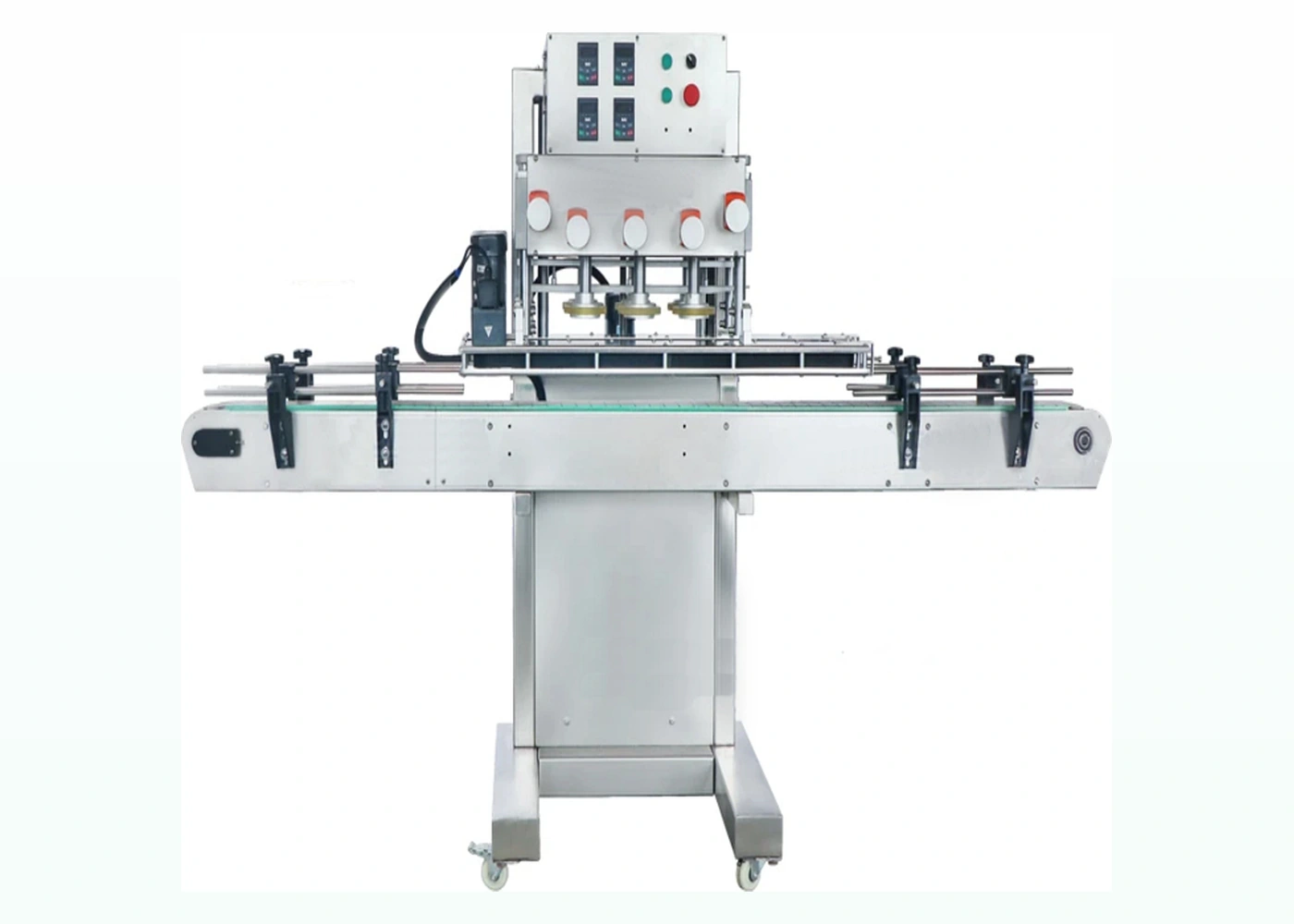
Machine overview
Higher-speed inline belt capper for round plastic bottles and production screw-cap lines.
3000–5000 bottles/hour
Screw caps by trial
35–120 mm bottle diameter
Clamps bottles for stable and accurate torque application.
Intuitive parameter setup and recipe storage.
Continuous-motion style capping for higher throughput.
Choose cap elevator or vibratory bowl depending on closure and line layout.
| Model | LU-XG440B class |
|---|---|
| Voltage | 110/220 V, 50–60 Hz |
| Power | Approx. 2 kW |
| Capacity | 3000–5000 BPH, material dependent |
| Bottle diameter | 35–120 mm |
| Bottle height | 60–200 mm |
| Machine size | Approx. 2000 × 900 × 1600 mm for capper |
| With cap elevator | Approx. 3453 × 1393 × 2243 mm |
| Controls | PLC + touchscreen |
| Integration | Upstream fillers / downstream inspection and labelling |
Final configuration, speed and tooling should be confirmed against real bottle and cap samples. Trial results may affect the exact quote, footprint and lead time.
Gallery
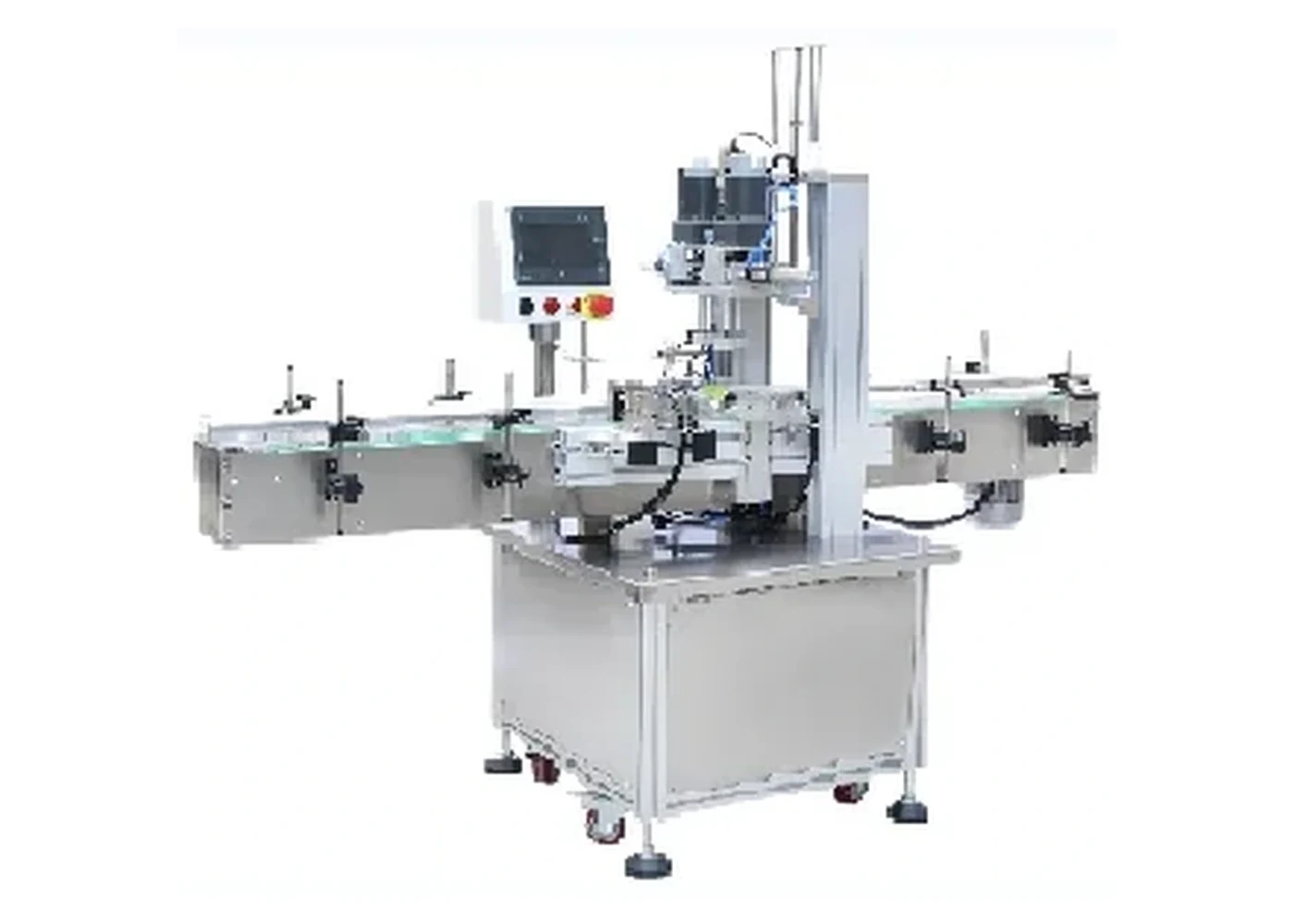
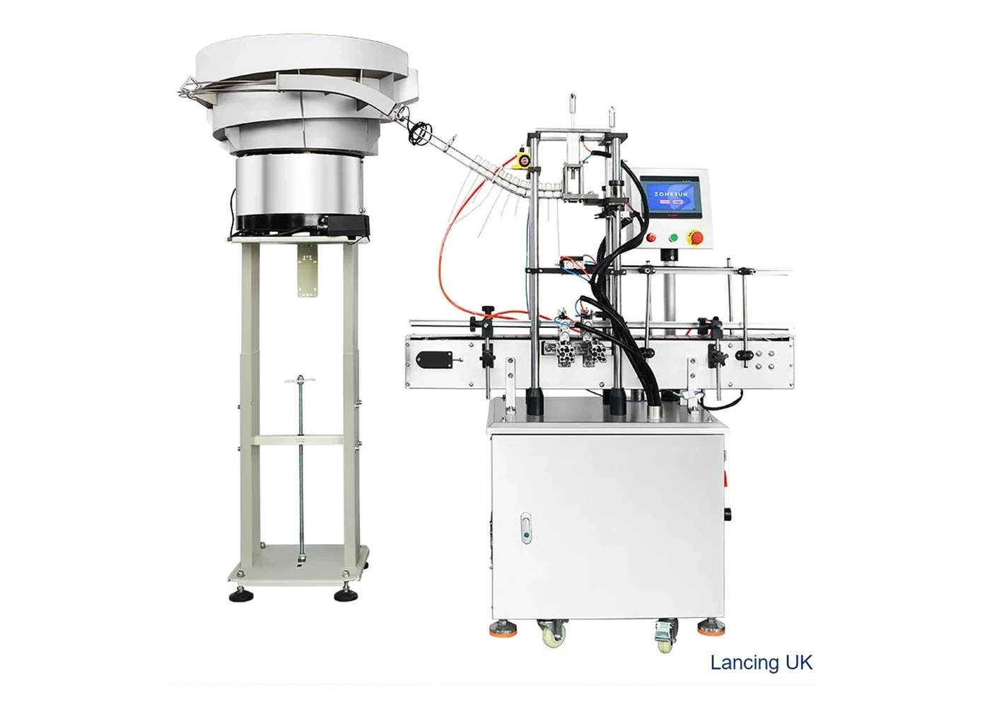
Only different machine visuals are shown here so the page does not repeat the same product photograph.
Compare
Desktop semi-automatic capper with automatic bottle clamping for low to medium volume screw-cap work.
View machine →Space-saving screw capper for sprays, pumps and standard screw caps on compact production benches.
View machine →Related pages
Compare capping machinery by bottle and closure type.
For spray, pump and taller threaded closures.
Plan tightening torque and sample trials.
Technical selection
A spindle capper is not simply a faster chuck. The bottle is controlled by side belts while several rotating contacts progressively tighten a pre-placed threaded closure. Cap placement, bottle spacing, belt pressure and spindle contact must therefore work as one process.
The supplied specification lists a capacity of 3,000–5,000 bottles per hour, material dependent, for bottles approximately 35–120 mm in diameter and 60–200 mm high. The capper is listed at approximately 2 kW with PLC and touchscreen control. The approximate capper footprint is 2000 × 900 × 1600 mm; the configured system with cap elevator is larger. These are screening figures and must be confirmed against the full line.
The cap has to reach the bottle in the correct orientation and sit squarely enough for the spindles to engage the thread. A feeder, chute and placement device should be tested with production caps, including difficult batches. Cap nesting, static, surface marking and inconsistent skirt geometry can all interrupt continuous running. Use Cap Feeders UK for feeder-specific selection.
Side belts should stabilise the bottle without distorting it or changing its height through the machine. The spindle contact material, angle, speed and pressure must suit the cap surface. Check smooth and ribbed caps separately. A closure can slip under the discs, become cross-threaded or reach an incorrect height even when the line appears to run continuously.
For each format, record rail width, side-belt position, spindle height and contact, speed and cap-feed settings. Agree cap height, torque or opening result, liner condition, thread engagement and closure integrity. The timed run should include normal cap replenishment, upstream bottle flow and downstream queue conditions. Define line controls, low-cap response, jam recovery, guarding and emergency-stop interfaces.
A single-head or semi-automatic machine can be more appropriate for unstable containers, short batches, frequent unrelated closures or formats that cannot be fed and pre-placed reliably. Compare the semi-automatic and automatic routes and the specialist Spindle Cappers UK resource before the final trial.
Buyer FAQ
Side belts stabilise the bottle while successive rotating spindle contacts apply tightening force to a cap that has already been placed on the thread.
No. The published capacity is material dependent. The agreed output must be demonstrated with production bottles, caps, cap presentation and the intended surrounding line.
Continuous side-belt control is easier when the bottle presents consistent contact surfaces and remains upright. Irregular, tapered or flexible packs need specific testing and may require another route.
Possibly, but contact material and pressure must be selected to transmit torque without slipping or marking. Smooth, decorative and soft-touch surfaces require sample trials.
The cap must be placed before tightening. Placement may be by chute, pick-and-place or another feeder system; that equipment is a separate part of the line specification.
Monitor cap placement, bottle stability, cross-threading, spindle slip, final cap height, torque or opening result, rejects, minor stops and the sustained line rate.
Continuous-line validation
The LU-XG440B-class route uses side support and successive spindle contact to tighten a pre-applied screw cap while the bottle continues along the conveyor. The published capacity is material dependent, so sustained output must be confirmed with the proposed cap-feed method, production bottle family, conveyor conditions and agreed finished-pack checks.
Side belts and guide rails must hold the container without crushing flexible walls, scuffing labels or lifting the bottle. The cap must be seated sufficiently for the first spindle contact to continue the thread rather than force a tilted closure. Lightweight, tapered or top-heavy bottles may need additional support or a different machine route.
| Variable | Typical failure signal | What to change or verify |
|---|---|---|
| Cap pre-placement | Cross-threading, high caps or the closure falling before spindle contact. | Feeder release, chute geometry, placement pressure, bottle timing and cap orientation. |
| Bottle support | Bottle rotation, leaning, label scuffing or inconsistent final height. | Side-belt height and pressure, rail position, conveyor condition and filled-pack stability. |
| Spindle setting | Loose caps, marked ribs, damaged skirts or variable removal result. | Wheel height, pressure, speed relationship, contact material and approved format settings. |
| Line balance | Frequent stops, uncontrolled queues or output below the headline figure. | Cap feeder capacity, infeed spacing, accumulation, downstream availability and control signals. |
This page covers the Lancing LU-XG440B-class screw-cap route. For a broader comparison of spindle capping layouts, applications and automatic line options use the dedicated Spindle Cappers UK resource rather than duplicating that specialist coverage here.
Provide production caps, filled bottles, intended conveyor speed, cap-feed method, upstream and downstream equipment and the quality checks used for release. The bottle-cap torque-test checklist and line-layout review help structure the evidence.
A successful isolated tightening test does not prove sustained automatic production.
Continuous-line stability
For the LU-XG440B-class route, the cap must be placed consistently before the bottle enters the tightening zone, while the side belts hold the pack without distortion and the spindle stages complete the closure without marking.
Confirm cap orientation, chute or handover pressure, placement height and thread-start condition before spindle contact.
Set guides and side belts for the least stable and least rigid format. Check for squeeze, spin, polish, lift and neck deflection.
Observe contact at each stage, final cap position and release. The closure should not be accepted from final torque or opening feel alone.
Test upstream spacing, downstream accumulation, cap replenishment and stop/restart so the capper is not judged only in an uninterrupted run.
Record belt, guide, spindle and feeder settings with identified change parts and first-off acceptance checks.
Measure accepted output with rejects, interventions and cap-feed events visible in the run record.
Question-led guidance
Continuous spindle capping depends on stable cap pre-placement, bottle control and coordinated motion.
Pre-tightening is the early controlled contact that stabilises a pre-placed cap and encourages the correct thread start before later spindle contacts complete tightening. Its setup depends on the closure and bottle. Confirm the resulting cap level using the cap-height and thread-start guide.
The bottle must travel through the capping zone without slipping, rotating unexpectedly or being pulled off-axis. Poor speed coordination can change spindle contact time and cap position. Include the final conveyor and control interface in the line-interface plan.
It depends on the closure, bottle stability, line speed, available machine length and how tightening is distributed through the process. Do not infer suitability from spindle count alone; prove thread start, cap condition and accepted closure performance during a representative run.
Possible causes include incomplete thread start, liner or component behaviour, inconsistent cap pre-placement, bottle movement, contamination or an acceptance method that checks only immediate torque. Use the closure-integrity process before increasing spindle pressure.
Send representative samples, target output and the current acceptance method so Lancing can review the correct capping route.
Continuous line control
Side belts, conveyor transfer and successive spindle contacts create a continuous process. Quality and safety checks must cover the entire movement path rather than the final spindle alone.
Confirm cap presence, pre-placement, thread-start attitude, bottle spacing and stable side-belt entry. A badly presented cap should not be tightened into a harder-to-detect defect.
Coordinate conveyor, side-belt and spindle contact while preventing access to nips and rotating parts. Test guards, stops and restart with accumulated bottles.
Inspect cap height, level, presence or visible damage where the bottle is stable, then track any failed pack to a confirmed reject point.
Continuous-line hand-off
A continuous belt/spindle capper can deliver stable throughput only when cap placement, bottle control and the downstream process share the same accepted line window.
| Interface | What to prove |
|---|---|
| Spindle exit to sealer | Bottle centreline, cap clearance, conveyor speed and enough distance for any pre-seal inspection or stabilisation. |
| Cap position | High, tilted or cross-threaded caps are identified before they become a sealing or downstream quality fault. |
| Torque consistency | Samples from normal running, each spindle-contact condition and after planned stops are measured using one controlled method. |
| Accumulation | The line prevents uncontrolled bottle contact, back-pressure or bottles remaining under an active sealing head. |
| Restart | The first packs after a stop are checked for cap position, torque method and seal integrity before normal production resumes. |
Buyer decision support
A belt or spindle route depends on the interaction between the moving contact surfaces, the cap and bottle restraint. A displayed speed or mechanical position is not an independent measurement of the finished closure. Keep the setup record and pack-test record separate.
Record spindle or belt condition, alignment and intended cap contact. Keep cap finish and contamination observations with the sample results.
Check whether the bottle stays controlled as the cap is tightened. A moving or distorted bottle changes the contact event and should be investigated before increasing the setting.
A second pass requires an approved incoming cap state and an acceptance method. It must not become an undocumented way to process high, tilted or damaged caps.
The control-principle comparison explains the distinction between frictional contact and a directly measured torque event. Use the re-tightening decision guide for an additional-stage enquiry, including any sealing history. These checks supplement the existing product specification without adding an unsupported output or monitoring claim.