01
Draw the line boundary
Show the machine before and after the capper, product flow, operator positions and who supplies each conveyor or interface.
Installation and integration
Utility and interface requirements depend on the selected machine and line scope. Confirm power, compressed air, conveyor arrangement, controls, access and responsibility before manufacture and installation.
Direct answer
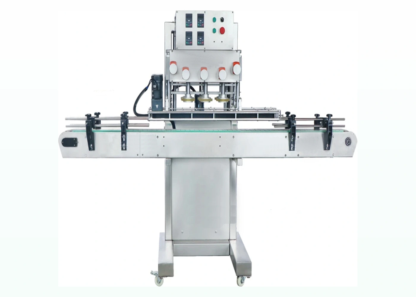
A screw capper may require electrical power only, or electrical power plus compressed air for clamps, actuators or cap handling. Automatic systems also need agreed conveyor height and direction, bottle spacing, cap availability, stop/start logic, fault signals, accumulation and interfaces with filling, labelling or inspection equipment.
Exact utility values must come from the selected machine specification. Final electrical and safety integration must be designed and assessed for the actual installation rather than copied from a generic machine description.
Decision evidence
Unclear boundaries create avoidable delays even when the capping machine itself is correctly selected.
| Interface group | Information to confirm | Why it matters |
|---|---|---|
| Electrical supply | Voltage, phase, frequency, isolator location, available load and local connection standard. | The machine must match the site supply and final installation design. |
| Compressed air | Whether the chosen configuration uses air, available pressure/quality and connection point. | Clamps, actuators or cap handling may depend on stable air supply. |
| Mechanical transfer | Conveyor height, direction, width, speed range, bottle spacing, guide clearances and accumulation. | Bottles must enter, remain controlled and leave without creating a line bottleneck. |
| Control signals | Run permissive, ready, fault, stop, no-cap/no-bottle status and upstream/downstream interlocks. | The line needs a defined response to normal operation and faults. |
| Safety boundary | Guarding interfaces, access, emergency-stop responsibility and line-level risk assessment. | The completed installation must be assessed as an integrated system. |
| Site access and service | Doorways, lifting route, floor, working space, cleaning method and maintenance access. | A machine that fits the layout drawing must still be deliverable, usable and serviceable. |
Practical method
A single controlled record helps the machine supplier, line integrator and site team close responsibilities.
Show the machine before and after the capper, product flow, operator positions and who supplies each conveyor or interface.
Record the selected machine’s actual power and air requirements against the available site services.
Define normal run, stop, fault, blocked/starved and restart behaviour for every relevant interface.
Check transport route, installation space, guarding, cleaning and maintenance access using the final footprint.
Include interface and controlled restart tests in FAT or SAT where the connected equipment is available.
Keep drawings, electrical information, settings, interface list and responsibilities with the installed line documentation.
Buyer questions
The final answer is model- and site-specific, but the information needed to confirm it is consistent.
No. Some configurations may be electrically operated, while others use compressed air for bottle clamps, capping-head movement, escapements or cap handling. Confirm the actual selected model and options rather than assuming from the machine category.
Confirm the site voltage, phase, frequency, available load, connection point, isolator arrangement and any local electrical requirements. The supplier’s final machine specification must be checked against the real installation, not a generic web-page value.
Typical interface needs include run permission, ready, fault, stop, blocked or starved condition and controlled restart, but the exact list depends on the line design. Agree signal ownership and expected behaviour for every machine before controls are finalised.
Responsibility must be defined for the actual project and supported by the completed line design and risk assessment. Do not assume that an individual machine emergency stop automatically provides the required integrated response across independently supplied equipment.
They affect machine handover, guide geometry, footprint, operator access and the position of upstream and downstream equipment. Late changes can require mechanical or control modifications even when the capping head and closure tooling remain suitable.
Continue the decision
Use the most relevant next page to prepare the pack, trial or machine specification.
Plan infeed, outfeed, accumulation, operator access and surrounding equipment.
Prepare the site, utilities, handover and operational checks for the selected machine.
Include interfaces, stops, restarts and line behaviour in the acceptance evidence.
Lancing can review the capper footprint, conveyor handover, controls boundary and installation route before the scope is fixed.