Bottle screw capping machine
Threaded bottle caps, jars and containers.
Screw capping machinery
Choose a screw capper by output, cap size, bottle stability and level of automation. Lancing UK can help check suitability before quotation.
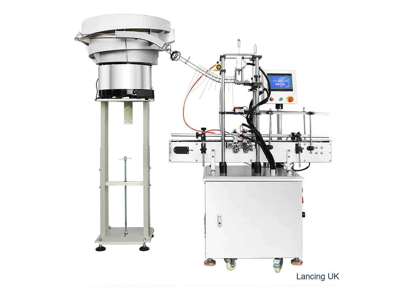
Desktop semi-automatic capper with automatic bottle clamping for low to medium volume screw-cap work.
View machine →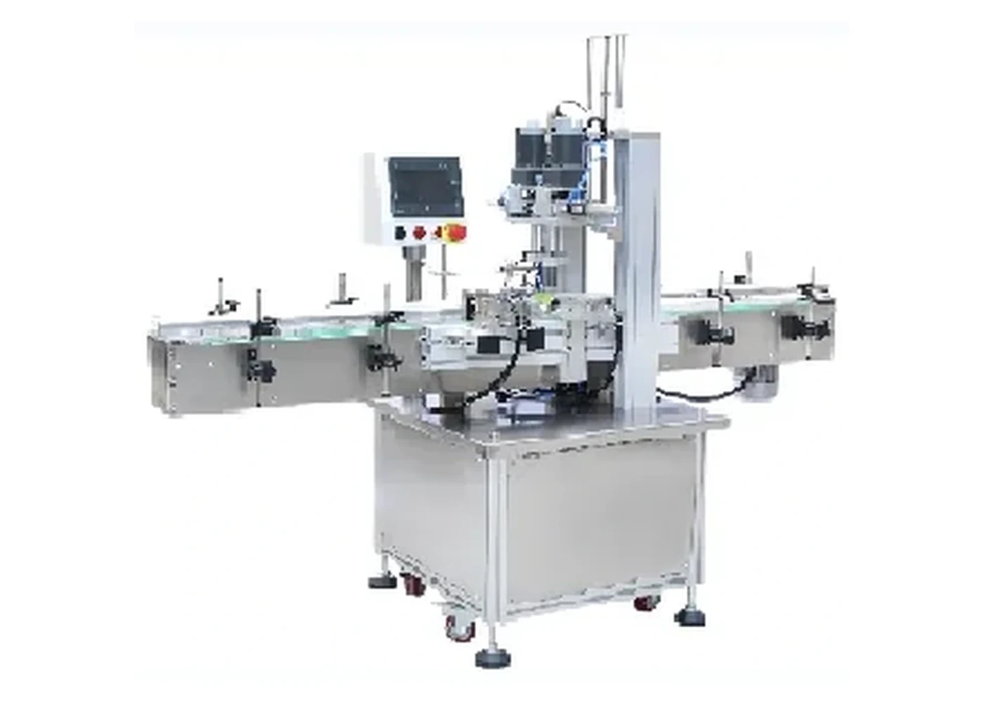
Space-saving screw capper for sprays, pumps and standard screw caps on compact production benches.
View machine →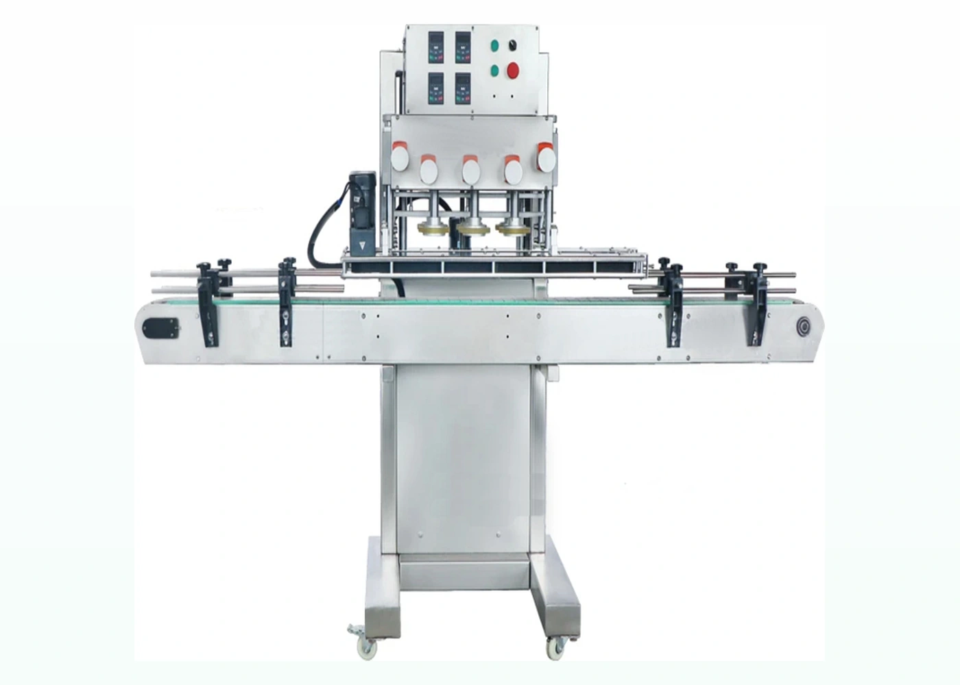
Higher-speed inline belt capper for round plastic bottles and production screw-cap lines.
View machine →The best machine choice depends on the complete closure process, not just the stated speed.
| Requirement | Why it matters | What to send us |
|---|---|---|
| Closure type | Standard screw caps, pumps and sprays may need different tooling and torque methods. | Cap samples, diameter, height, thread and liner information. |
| Container stability | Tall or lightweight bottles may need stronger side guides or clamping. | Bottle drawing, material, diameter, height and filled weight. |
| Target output | Output decides whether semi automatic, compact inline or high-output automatic is sensible. | Bottles per minute or bottles per hour target and shift pattern. |
| Cap feeding | Automatic cap presentation can dominate line reliability. | Photos of caps, orientation requirement and available floor space. |
Buyer routes
Use these pages to narrow the machinery route by the way customers search for bottle capping equipment.
Threaded bottle caps, jars and containers.
Sprays, pumps and taller closures.
Compare output, labour and automation level.
Machine selection
The range moves from operator-assisted chuck capping to compact inline, automatic single-head and continuous belt/spindle systems. The correct route depends on how the cap reaches the bottle and how the bottle is supported during tightening.
| Machine route | Cap presentation | Pack control | Best project fit | Evidence to send |
|---|---|---|---|---|
| Semi-automatic chuck capper | Normally operator placed. | Automatic clamp or locator supports the bottle. | Short to medium batches and mixed formats. | Bottle and cap samples, target torque, operator cycle and batch length. |
| Compact desktop/inline capper | Manual or configured assisted placement. | Guides, fixtures and a compact conveyor where specified. | Labs, pilot rooms and constrained production spaces. | Available footprint, bottle stability, closure height and required output. |
| Automatic single-head capper | Manual placement or an optional bowl/elevator route. | Inline guides, sensors and bottle fixtures. | Regular production requiring repeatable automatic cycling. | Cap feed requirement, line direction, bottle spacing and controls interface. |
| Automatic belt/spindle capper | Pre-placed or automatically presented screw caps. | Side belts stabilise the container through multiple tightening contacts. | Continuous higher-output lines with repeatable packs. | Filled bottle samples, cap batches, conveyor height and timed-run target. |
Validation
Check cap diameter and height, rib pattern, smooth finish, liner, tamper feature and thread start. The contact method must grip securely without marking the finished closure.
Check height, width, neck finish, rigidity, shoulder geometry, filled weight and centre of gravity. The least stable format often determines the guide, clamp or side-belt arrangement.
Agree the torque or opening requirement, cap height, thread engagement, liner condition, leakage check and sustained output under the intended cap-placement method.
Quotation inputs
Provide representative production bottles and caps, including known difficult variations. State the bottle and cap dimensions, the product or filled weight, normal batch size, required output and whether the closure is manually placed or automatically fed. Add photographs of the available line space and details of the filler, conveyor, inspection or labeller that the capper must connect to.
Where a quality standard already exists, include the method used to judge a finished pack. This may be an application or removal torque window, cap-height band, visual thread engagement, liner condition, leakage test or agreed opening feel. The test condition should be recorded with the result so the same acceptance method can be repeated during commissioning.
Use the screw capper buyer guide, the torque-test checklist and the quotation checklist before sending an enquiry.
Operating-method comparison
A useful shortlist separates cap presentation, bottle control and sustained workflow. The capping head is only one part of the production method.
| Route | How caps reach the bottle | How the bottle is controlled | Best operational fit | Evidence needed before quotation |
|---|---|---|---|---|
| Handheld or bench chuck capper | The operator places each cap and presents the bottle. | Operator grip, bottle nest or anti-rotation support. | Short batches, development work and varied formats where flexibility matters more than continuous transfer. | Representative bottle and cap samples, target opening result, batch size and operator method. |
| Semi-automatic single-head capper | The operator normally places the cap; the machine controls the tightening cycle. | Clamp, locator or nest prevents the container rotating during application. | Repeatable batch production where hand tightening is no longer consistent but manual loading is still practical. | Filled bottle weight, cap geometry, accepted finished pack and a timed operator-assisted trial. |
| Automatic single-head system | Caps may be placed by an operator or supplied through a feeder, chute and placement device. | Guides, stops, starwheel or indexed conveyor control the bottle at the capping point. | Regular production that needs controlled bottle presentation and the ability to handle taller pumps, sprays or specialist screw closures. | Cap feeding trial, bottle transfer sequence, stop/start signals, line layout and sustained output requirement. |
| Belt or spindle capper | A correctly oriented cap is pre-applied before the bottle passes through the tightening station. | Side belts, guide rails and conveyor support keep the bottle upright while successive spindle wheels tighten the closure. | Continuous lines using stable bottle families and screw caps that can be fed and pre-placed consistently. | Full pack family, cap-feed handover, bottle stability evidence, line speed, accumulation and agreed acceptance checks. |
Cap diameter alone is not enough. Thread start, cap height, rib pattern, liner, tamper feature and surface finish influence the chuck, insert, feed route and tightening method. Use the chuck and change-parts guide before assuming one tool will cover the whole range.
Measure a representative run that includes cap replenishment, operator handling, line stops and normal changeovers. A short isolated cycle can overstate production output. The screw capper buyer guide explains the evidence needed for a stronger shortlist.
This site owns threaded screw-cap tightening. For wider bottle-capping comparison use Bottle Cappers UK; for other closure technologies use Capping Machines UK. Detailed automatic cap-feeding work belongs with Cap Feeders UK.
Include the least stable bottle, every closure geometry, target output, current acceptance method and the equipment before and after the capper.
Selection evidence
A defensible shortlist connects the closure and bottle to sustainable production, cap presentation, changeover work and the evidence that will be used at trial and handover.
| Decision | Evidence to prepare | Technical resource |
|---|---|---|
| Machine automation level | Good-pack requirement, batch length, operator tasks, cap placement and connected-line constraints. | Capacity planning |
| Tooling and bottle control | Format extremes, cap finish, neck position, bottle stiffness, filled weight and accepted reference packs. | Sample submission |
| Scope and interfaces | Pack schedule, infeed/outfeed, feeder route, utilities, controls, documentation and support requirements. | URS specification |
| Acceptance and handover | Pass/fail checks, timed run, stop/restart, changeover, deviation and training evidence. | FAT and SAT guide |
This reduces assumptions and makes it easier to compare a semi-automatic chuck capper, automatic single-head system and continuous belt/spindle capper on the same production duty.
Question-led guidance
Machine type should follow the complete pack, cap-presentation method and accepted production duty.
Bottle material is one factor, but rigidity, shape, neck support, filled weight and surface finish usually matter more than the material name alone. Lightweight plastic, rigid glass and handled containers require different support evidence. Review lightweight bottle handling where wall flexibility is a concern.
It can be supplied as part of an integrated system or as a separate project element. The feeder, chute, escapement and capper handover must still be treated as one process. See the cap-feeder handover guide for the acceptance points.
Include future formats only when they are genuinely planned and supported by samples or drawings. Record the format extremes and likely change parts so adjustment range and tooling can be considered without guessing. The measurement guide lists the useful dimensions.
Compare the defined pack family, cap placement or feeding scope, tooling, sustainable workflow, line interfaces, utilities, trials, acceptance method, installation and support. A lower headline machine price is not equivalent when one quote excludes the feeder, change parts, controls handover or site work.
Send representative samples, target output and the current acceptance method so Lancing can review the correct capping route.
Complete capping cell
The machine route should also cover bottle control, cap presentation, quality inspection, safe access, cleaning and recovery from normal disturbances.
| Route | Cap and bottle handling | Quality and operating evidence |
|---|---|---|
| Bench or semi-automatic chuck | Operator places the cap; the machine holds and tightens the pack. | Prove operator cycle, bottle restraint, chuck release, first-off checks, safe foot-pedal or start control and cleaning of pack-contact tooling. |
| Compact or automatic single-head | Bottles index or pass through guides; caps may be manually placed or fed. | Prove cap handover, no-bottle/no-cap states, stop/restart sequence, reject route and access for adjustment and cleaning. |
| Belt or spindle capper | Side belts stabilise the bottle while successive contacts tighten a pre-placed cap. | Prove belt and conveyor coordination, cap level, spindle contact, line guarding, post-cap inspection and rejection under continuous flow. |
Choose the visible defects, inspection method, bottle tracking and confirmed reject sequence.
Define the installed risk boundary, intervention tasks, isolation and line-stop behaviour.
Control contamination zones, compatible methods, tooling identity and first-off release.
Before machine selection
A bench, compact, single-head or spindle capper should be selected against the same approved pack evidence. That avoids comparing nominal cycle rates while leaving the bottle, cap, torque and downstream process undefined.
| Decision | Evidence to provide | Why it changes the machine route |
|---|---|---|
| Bottle and cap interface | Drawings, neck finish, cap construction, liner or tamper feature and production samples. | Determines whether the pack fits, how the thread starts and which chuck, insert or spindle contact is practical. |
| Torque method | Approved pack, tester range and fixture, test direction, timing and acceptance record. | Separates a repeatable finished closure from an arbitrary machine setting. |
| Cap placement | Manual placement, elevator, bowl, track, pick-and-place or pre-threading requirement. | Controls sustainable output, operator work and automatic-line complexity. |
| Downstream sealing | Induction liner, sealer type, conveyor speed, inspection method and stop/restart requirement. | Connects cap application to liner contact and the final sealed-pack result. |
Use drawings, samples and variation evidence before tooling is approved.
Keep instrument, fixture, timing and result type consistent through trials.
Prove the hand-off from seated cap to foil-seal inspection and line recovery.
Buyer decision support
An adjustable capper, a recorded application signal and a sampled removal-torque result are not interchangeable. Confirm the control, the evidence and the response to an unacceptable pack as separate quotation items.
| Scope item | Question for the supplier | Evidence to retain |
|---|---|---|
| Control | What adjustment or command changes the tightening operation? | Named head or contact arrangement, setting procedure and approved format record. |
| Measurement | Is torque commanded, inferred, directly measured or checked off the line? | A defined measurement point, units, instrument or signal basis and sample method. |
| Fault handling | What happens to a cap that is high, tilted, missing or outside a monitored limit? | The actual stop, segregation or reject arrangement, where specified. |
| Package release | What must the finished bottle satisfy after the intended processing and storage? | Opening, cap-position, liner, tamper and integrity checks appropriate to the approved pack. |
Use the torque-control comparison when comparing automation proposals. For product investigations, the retained-pack test framework explains why the state and age of the sample matter. The current product pages remain the source of model-specific information; no additional monitoring or servo capability is implied.