S
Speed
20–60 bottles/min
Automatic Series
A pneumatic inline automatic screw capping machine for production lines that need a stronger balance of throughput, repeatability and flexibility. It handles screw caps, spray caps and pump caps with adjustable guides and stable torque control.
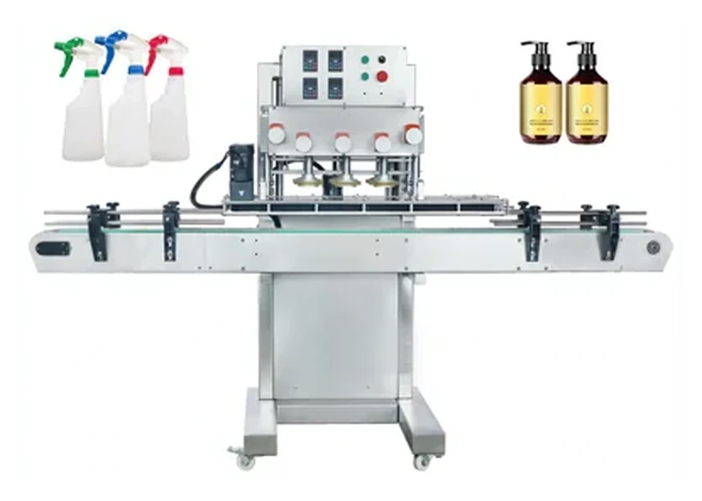
Machine overview
Inline automatic capping machine for spray bottles, pump closures and general screw caps.
20–60 bottles/min
18–70 mm caps
20–160 mm bottle diameter
Designed for continuous production after filling and before labelling.
Guides and clamps adapt to different bottle styles.
Automates start/stop and improves consistency.
Can integrate with a bowl or elevator where required.
| Model | LU-XG16 class |
|---|---|
| Working voltage | AC 220/110 V, 50–60 Hz |
| Bottle height | 30–300 mm |
| Cap diameter | 18–70 mm |
| Bottle diameter | 20–160 mm |
| Working speed | 20–60 bottles/min |
| Working pressure | 0.4–0.6 MPa |
| Dimension | Approx. 1930 × 740 × 1600 mm |
| Machine weight | Approx. 150 kg |
| Feeding | Cap bowl or elevator optional |
Final configuration, speed and tooling should be confirmed against real bottle and cap samples. Trial results may affect the exact quote, footprint and lead time.
Gallery
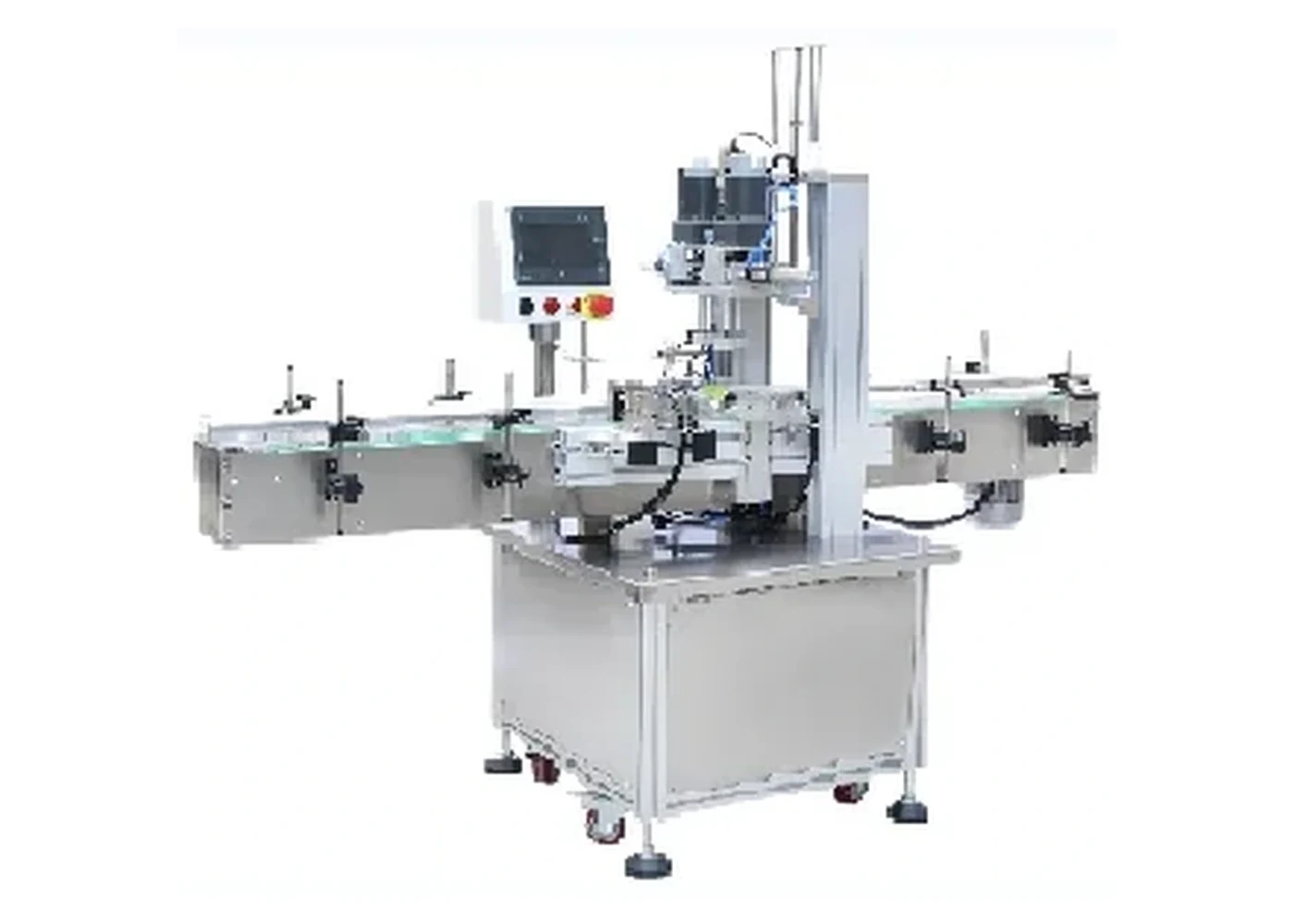
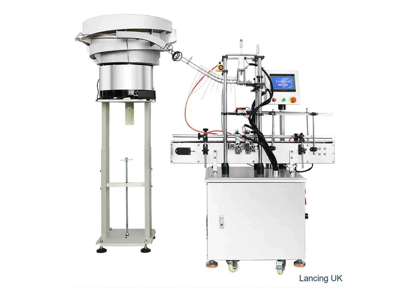
Only different machine visuals are shown here so the page does not repeat the same product photograph.
Compare
Desktop semi-automatic capper with automatic bottle clamping for low to medium volume screw-cap work.
View machine →Space-saving screw capper for sprays, pumps and standard screw caps on compact production benches.
View machine →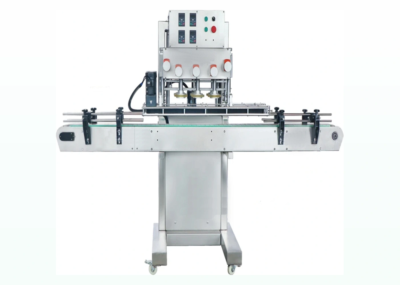
Higher-speed inline belt capper for round plastic bottles and production screw-cap lines.
View machine →Related pages
Compare capping machinery by bottle and closure type.
For spray, pump and taller threaded closures.
Plan tightening torque and sample trials.
Technical selection
This platform brings bottle detection, inline handling and automatic capping into one controlled cycle. It can be considered when manual tightening is no longer consistent or when the capper must sit between filling and labelling. The final system still depends on whether an operator places each cap or an automatic feeder presents it.
The supplied page lists bottle height from 30–300 mm, bottle diameter from 20–160 mm, cap diameter from 18–70 mm and working speed from 20–60 bottles per minute. Working pressure is listed at 0.4–0.6 MPa and the approximate machine size is 1930 × 740 × 1600 mm. A cap bowl or elevator is optional. These figures must be confirmed for the actual bottle, closure, feed method and line layout.
Automatic tightening cannot correct a cap that arrives tilted, reversed or on the wrong thread start. For manual placement, confirm the operator can sustain the target pace safely. For automatic feeding, test cap nesting, orientation, chute handover and placement on the moving or indexed bottle. Specialist feeder selection belongs with Cap Feeders UK.
Guides and fixtures should support the container through detection, cap engagement and tightening. Tall, flexible or lightweight bottles may need additional support. Agree the finished cap height, application or removal torque method, liner and tamper-feature condition, leakage or closure-integrity check and acceptable cosmetic result.
Record the approved guide positions, head height, tooling, sensor positions and speed for each format. The project scope should define line start/stop, queue signals, low-cap response, emergency-stop interface and recovery after a jam. Routine checks should include tooling condition, guide security, sensors, pneumatic supply and product contamination around the capping head.
Send all bottle and cap variants, filled weights, required output, batch pattern, cap-placement method, available floor space, conveyor height, line direction and upstream/downstream equipment. Use the cap feeder versus manual placement guide and line-layout review before finalising the scope.
Buyer FAQ
No. This page describes an automatic inline single-head/pneumatic capping route. A belt/spindle machine uses successive rotating contacts and is a separate option.
The supplied specification lists a cap bowl or elevator as optional. The correct feeder depends on the exact cap and must be confirmed by sample testing.
Bottle stability, cap placement, closure geometry, sensor spacing, tightening time and downstream accumulation all affect the sustainable result.
A platform may be configured for several closure families, but tooling, guides, head height and presentation method can differ. Each format must be included in the approved scope.
Confirm start/stop, bottle-present detection, low-cap condition where a feeder is used, queue control, emergency-stop interfaces and the recovery sequence after a stoppage.
A spindle route may be better for continuous higher-output lines with stable bottles and consistently pre-placed threaded caps.
Automatic-line evidence
The LU-XG16-class machine can only tighten a cap consistently after the closure has been presented correctly and the bottle has reached the capping point in a repeatable position. An automatic capper therefore has to be trialled as a sequence: cap supply, orientation, placement, bottle control, tightening, release and transfer to the next line stage.
The run video shows the relationship between conveyor transfer, bottle control and the capping station. It does not establish suitability for a different cap, bottle or output. The final system should be confirmed with representative production samples and an agreed test that includes normal stops, restart conditions and cap replenishment.
| Control point | Question to settle | Trial evidence |
|---|---|---|
| Cap feeder handover | Can the closure be oriented and released without nesting, scuffing, bridging or unstable presentation? | Normal production caps, low-level and refill conditions, and a record of every misorientation or stoppage. |
| Bottle indexing | Does the bottle arrive in the same position at steady running and after line stops? | Filled bottles across the intended size range, including the least stable format. |
| Tightening setup | Does the selected chuck or head grip the cap without marking it or distorting the bottle? | Approved settings, finished-pack checks and samples from start, middle and end of the run. |
| Line integration | Can the filler, capper, labeller and conveyors stop and restart without creating an uncontrolled queue? | Layout, conveyor direction and height, signal list and agreed accumulation strategy. |
Send caps, filled bottles, the required line sequence and the acceptance checks used by production or quality teams.
Automatic sequence
Automatic tightening depends on a clean transition from bottle detection and stopping to cap presentation, thread start, head contact, release and outfeed. Each interface should have an observable acceptance check.
| Sequence point | Control question | Trial evidence |
|---|---|---|
| Bottle arrival | Does the sensor detect the full format range and stop each bottle squarely? | Format extremes at normal conveyor condition. |
| Cap handover | Is the closure oriented, available and presented without damage or forced correction? | Feed/replenishment and recovery from a cap interruption. |
| Thread start | Does the cap locate before final tightening force develops? | Side-view observation, cap height and cross-thread inspection. |
| Head action | Does the tool contact the intended closure surface and release cleanly? | Tool identity, pack finish and repeatable cycle record. |
| Outfeed | Can the finished pack leave without back pressure, tip or recontact? | Connected-line or simulated accumulation test. |
Question-led guidance
Automatic operation must include bottle detection, cap availability, faults and controlled restart.
The intended control sequence should prevent an unsafe or meaningless capping cycle and identify which packs need inspection. Detection and response depend on the machine and cap-presentation scope. Define the required signals and fault behaviour in the line-interface schedule.
The line should return to a known state, clear or identify queued bottles and caps, restore spacing and require first-off inspection where needed. Restart behaviour must be tested with the connected feeder and conveyors rather than assumed from steady running.
The project may use operator inspection, sensors, measurement or downstream inspection depending on the accepted pack and line scope. Define the defect to detect, the reject method and what happens to uncertain packs. The closure-integrity guide helps define the acceptance evidence.
Some layouts can use operator-placed caps while retaining automatic bottle handling and tightening, but the sustainable output and safe operator position must be proved. If manual placement becomes the constraint, a feeder and controlled handover can be added to the project scope.
Send representative samples, target output and the current acceptance method so Lancing can review the correct capping route.
Automatic quality control
The LU-XG16-class capping route can only deliver controlled good-pack output when the line defines what happens to bottles with no cap, a high or tilted cap, a feed interruption or an unconfirmed reject.
| Line event | Control question | Acceptance evidence |
|---|---|---|
| No bottle at the capping point | How are capping and cap placement inhibited without losing the sequence? | Challenge the sensor and confirm no unsafe or uncontrolled cycle occurs. |
| No cap or incorrect handover | Does the bottle stop, bypass, reject or create an alarm? | Test the defined response and bottles already within the controlled zone. |
| High, tilted or missing cap | Where is the defect visible and how is the failed bottle tracked? | Use accepted and known-defect packs to challenge detection and reject confirmation. |
| Conveyor stop and restart | How are bottles between sensors, capping and rejection retained in sequence? | Stop at several positions and confirm correct recovery without duplicate or missed actions. |
| Repeated failures | When should the machine alarm or stop the wider line? | Test the agreed consecutive-fault rule and operator recovery method. |
Downstream sealing
Where a lined screw cap is induction sealed, the automatic capper must create a consistent seated condition before the bottle reaches the sealer. Cap feed, thread start, bottle restraint and cap height should be checked together with foil-seal evidence.
Prevent mixed lined and unlined closures or materially different liner lots entering the automatic feed route.
Detect high, tilted, cross-threaded or missing caps before they enter the induction field where practical.
Coordinate capper demand, conveyor speed, sealer enable and stop/restart behaviour so bottles are not left in an uncontrolled sealing position.
Buyer decision support
For an automatic capping enquiry, name the required evidence separately from the mechanical cycle. An adjustable tightening action does not by itself establish per-bottle measurement, stored torque data, rejected-pack tracking or approval of the final seal.
| Requirement | Include in the enquiry |
|---|---|
| Control method | The closure supplier’s approved requirement and the adjustment, head or drive arrangement to be confirmed. |
| Monitoring requirement | What signal must be available, whether it is measured or inferred, and how it is associated with the pack. |
| Fault disposition | Required line stop, segregation or reject confirmation; distinguish optional functions from included equipment. |
| Post-process evidence | The test state after any induction sealing, cooling or storage stage, and who approves package release. |
Compare torque-control technologies before treating two quotations as equivalent. A proposed second tightening station also needs a defined re-torquing process brief. The trial must confirm what the quoted configuration supplies; no additional servo, measurement or reject feature is claimed for this model.