S
Speed
20–60 bottles/min
Semi Series
A compact semi-automatic screw capping machine for manufacturers that need repeatable torque without committing to a fully automatic line. The machine uses automatic bottle clamping, manual or automatic cycling and quick chuck changes for different screw closures.
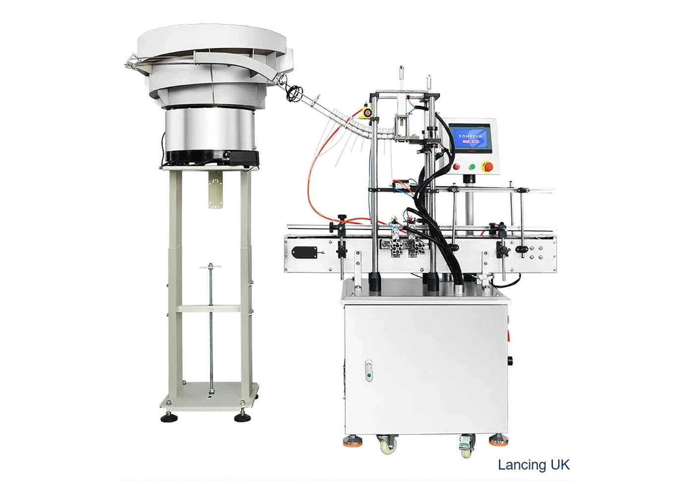
Machine overview
Desktop semi-automatic capper with automatic bottle clamping for low to medium volume screw-cap work.
20–60 bottles/min
20–60 mm caps
100–300 mm bottle height
Auto clamps bottles during capping for accuracy and repeatability.
Cap diameters 20–60 mm, with larger sizes available by configuration.
Foot-pedal or automatic cycling to suit the operator workflow.
Swap chucks and guides to run different formats on the same bench machine.
| Model | LU-XG6100 class |
|---|---|
| Bottle height | 100–300 mm |
| Cap diameter | 20–60 mm; custom sizes subject to trial |
| Working speed | 20–60 bottles/min, format dependent |
| Working mode | Manual / automatic |
| Bottle holding | Automatic clamping structure |
| Voltage | AC 220/110 V, 50–60 Hz |
| Power | 120 W |
| Air connection | OD 8 mm for clamping |
| Machine size | Approx. 475 × 350 × 500 mm |
| Net / gross weight | Approx. 28 kg / 35.5 kg |
Final configuration, speed and tooling should be confirmed against real bottle and cap samples. Trial results may affect the exact quote, footprint and lead time.
Gallery
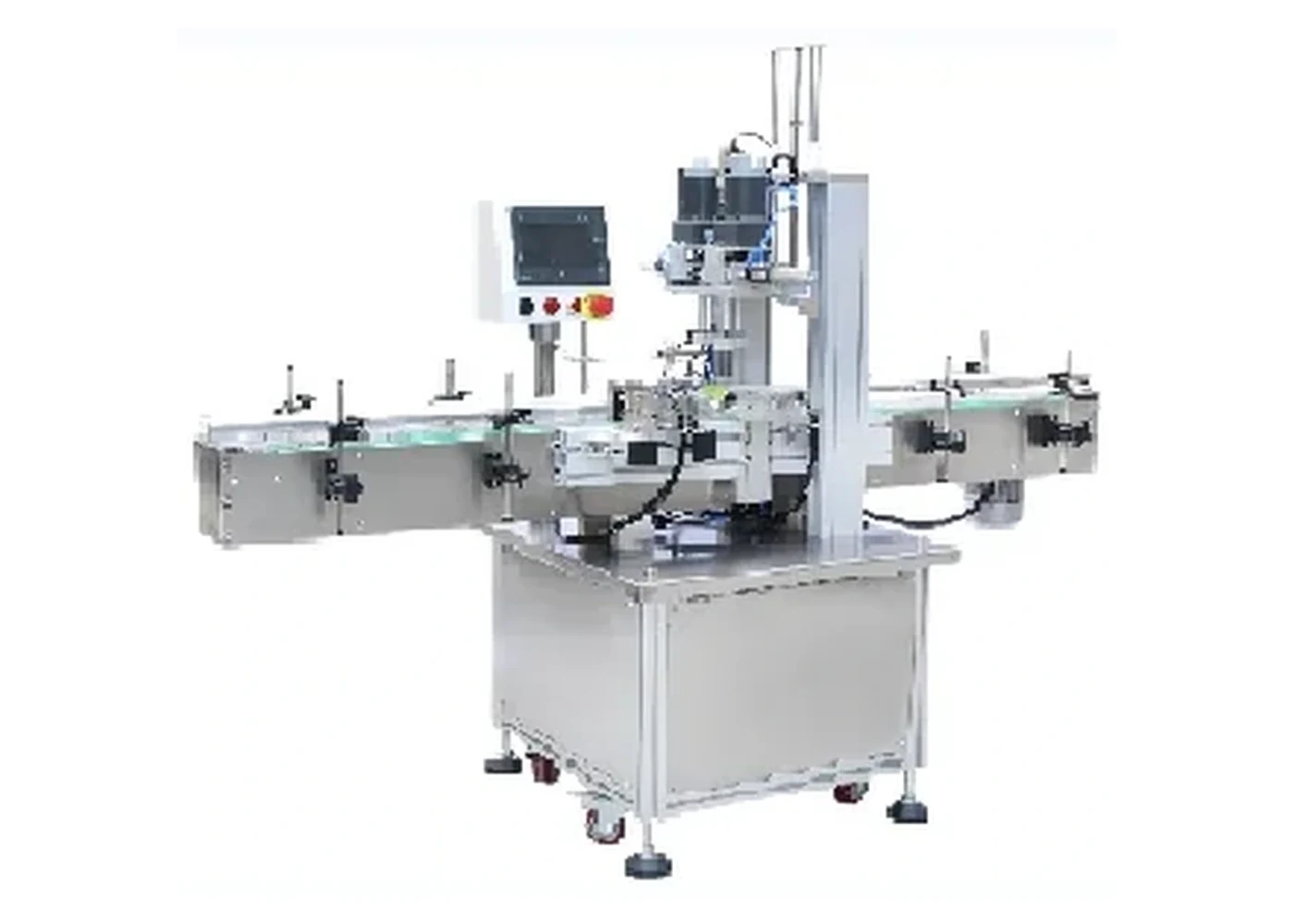
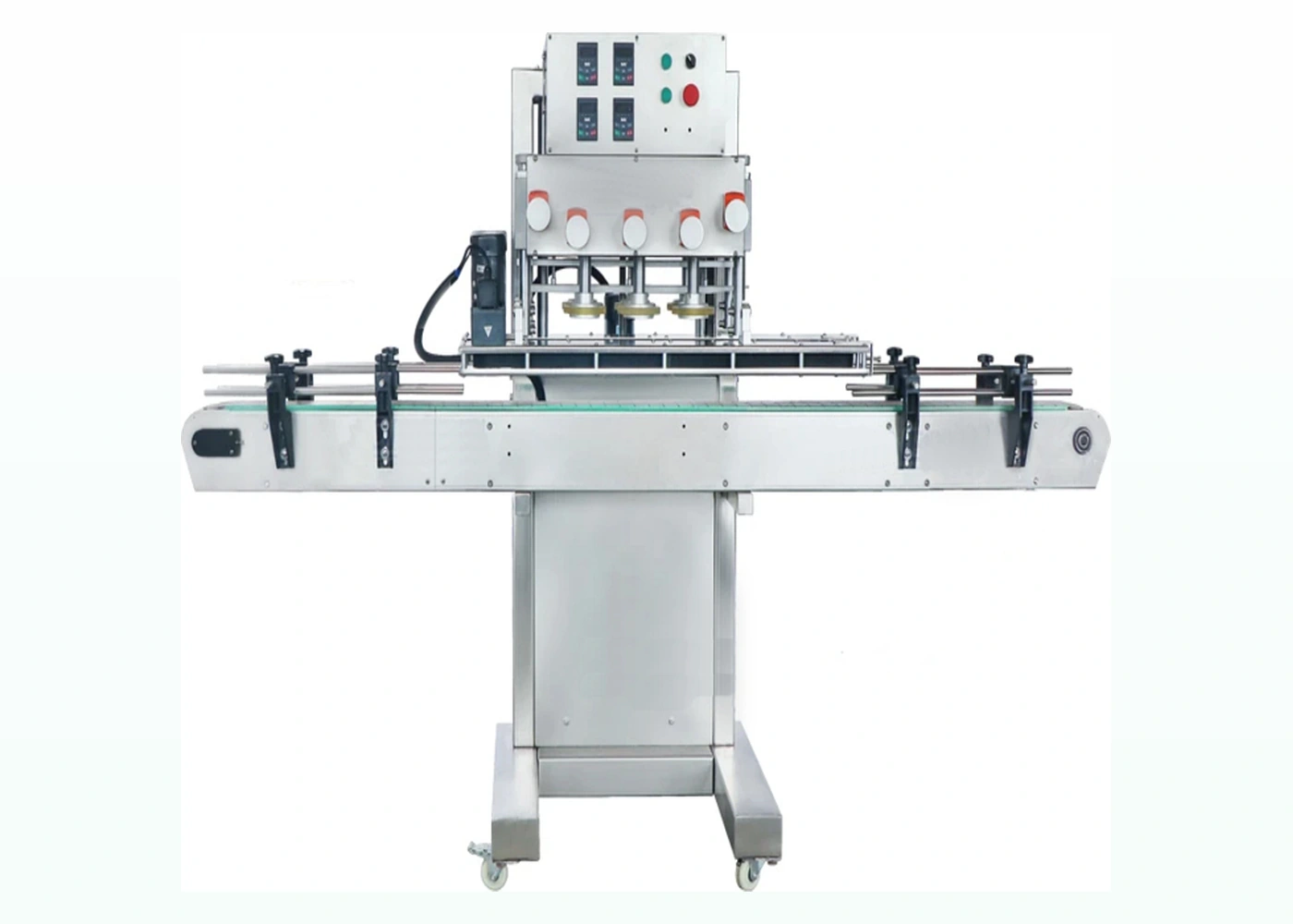
Only different machine visuals are shown here so the page does not repeat the same product photograph.
Compare
Space-saving screw capper for sprays, pumps and standard screw caps on compact production benches.
View machine →Higher-speed inline belt capper for round plastic bottles and production screw-cap lines.
View machine →Related pages
Compare capping machinery by bottle and closure type.
For spray, pump and taller threaded closures.
Plan tightening torque and sample trials.
Technical selection
The operator places the threaded closure and presents the bottle; the machine then clamps the container and drives the capping chuck. This separates cap placement from controlled tightening and can reduce the variation associated with hand tightening while retaining flexibility for short batches and frequent changeovers.
The supplied specification lists bottle height from 100–300 mm, cap diameter from 20–60 mm and a working speed of 20–60 bottles per minute, with custom sizes and output subject to the production format and trial. The machine is listed with manual and automatic cycling modes, a 120 W drive and an OD 8 mm air connection for clamping. These figures are a screening envelope, not an acceptance result.
Confirmation should use representative bottles at production weight, caps from normal supply and the intended operator workflow. Record cap placement, clamp position, chuck or insert, height setting and the agreed finished-pack checks. A timed run should include normal replenishment and handling rather than measuring only the capping stroke.
The chuck must contact the cap securely without polishing ribs, marking decorative surfaces or deforming the skirt. The bottle clamp must resist rotation but should not damage flexible walls. Check the thread start before tightening, then inspect final cap height, liner condition and any tamper feature. A cap that feels tight can still be cross-threaded or sitting high.
Format changes normally involve chuck or insert selection, capping-head height, bottle locator and clamp pressure. Keep approved settings with the format record and inspect contact surfaces for wear or product contamination. Cleaning should protect electrical and pneumatic components and follow the supplied machine manual; the product-contact and hygiene method must be agreed for the application.
This route is usually a standalone operator station. Where a conveyor, filler or labeller is added, confirm bottle spacing, operator access, accumulation and safe handover. Send bottle and cap samples, target output, batch length, accepted torque or opening requirement, available power and air and photographs of the production area. Use the bottle-cap torque-test checklist and chuck and change-parts guide before requesting the final configuration.
Buyer FAQ
The supplied page describes an operator-assisted semi-automatic route. Automatic cap feeding should be treated as a separate, sample-led project rather than assumed from the base machine.
The automatic clamping structure should be set around the production bottle so it prevents rotation without crushing, distorting or marking the pack.
No. The published figure is format dependent. The sustained result must be confirmed with the actual bottle, cap, operator method and agreed trial conditions.
Not necessarily. Diameter is only one variable; cap height, rib pattern, surface finish, liner and external geometry can require different inserts or dedicated chucks.
Confirm chuck condition, height, bottle clamp position, thread start, final cap height, torque or opening result and the first accepted production samples.
Move to an automatic inline or spindle route when manual cap placement, operator cycle or bottle transfer prevents the required sustained output.
Production acceptance
The LU-XG6100-class route separates manual cap placement from a controlled clamping and tightening cycle. That can improve repeatability, but the sustained result still depends on the operator presenting a correctly started cap, the clamp holding the production bottle without distortion and the chuck releasing cleanly after tightening.
Test the lightest and heaviest filled bottle conditions, the shortest and tallest formats within the intended range and caps from normal supply batches. A flexible empty container may behave differently once filled, while a tall or top-heavy bottle can require a different locator or clamp position. Include any cap with a liner, tamper feature or decorative surface that changes the permitted contact area.
A practical run should include picking up the bottle, placing and thread-starting the cap, positioning the container, initiating the cycle, removing the finished pack and replenishing nearby caps. Record interruptions caused by cap handling, bottle instability or operator reach. This gives a more useful sustained output than timing the tightening stroke in isolation.
| Acceptance stage | Check | Evidence to retain |
|---|---|---|
| Before the run | Approved chuck or insert, head height, bottle locator, clamp pressure and cycle mode. | Format record, sample photographs and the accepted reference pack. |
| During the run | Cap starts squarely, bottle does not rotate, chuck does not mark the closure and the operator can work without unsafe reach or strain. | Timed run notes, stoppage reasons and examples from the start, middle and end of the batch. |
| After the run | Cap height, thread engagement, liner condition, removal result, leakage requirement and any tamper feature. | Accepted and rejected samples labelled with machine settings and test timing. |
If manual cap placement becomes the controlling bottleneck, if operator variation affects thread start or if the required output cannot be sustained with safe handling, compare the automatic single-head screw capper and the belt / spindle route. Use the bottle-cap torque guide to define the finished-pack checks before changing automation level.
Operator-led capacity
For the LU-XG6100-class route, sustainable output depends on how the operator presents the cap, locates the bottle, starts the cycle, removes the finished pack and performs the agreed checks.
| Cycle element | Trial observation | Acceptance evidence |
|---|---|---|
| Cap placement | Can the operator place each closure squarely without correcting the thread start? | Observed placement method and rejected/accepted examples. |
| Bottle location | Does the bottle enter the locator or clamp without tip, squeeze or delay? | Stable format extremes in empty and agreed filled condition. |
| Chuck contact and release | Does the tool grip without marking and release without lifting the bottle or actuator? | Tool identity, cap finish inspection and repeatable release. |
| Operator workload | Can loading, unloading, inspection and cap supply be sustained safely through the intended batch? | Timed good-pack run with interventions and rejects recorded. |
Question-led guidance
Semi-automatic output and repeatability depend on the operator workflow as well as the capping head.
Yes. Product, oil, powder or moisture on the cap exterior can reduce chuck grip, mark the closure or make results inconsistent. The trial should reproduce the filling-to-capping handover and check whether cleaning, drip control or a different contact surface is needed. Closure and liner condition should also be recorded.
Use a timed run that includes picking bottles, placing caps, presenting the pack, operating the cycle, removing finished packs and replenishing components. A short isolated capping cycle does not show sustainable output or fatigue. Record good packs and interruptions during the normal batch pattern.
Height variation can change head travel, cap contact, clamp position and seated result. Measure the actual production range and check the shortest and tallest acceptable bottles. The bottle and cap measurement guide provides a repeatable format record.
A foot pedal can let the operator keep both hands available for bottle and cap presentation, but the complete task and safe operating method must be assessed for the machine. Compare pedal and automatic cycling during the trial and approve the route that produces a controlled, sustainable workflow.
Send representative samples, target output and the current acceptance method so Lancing can review the correct capping route.
Operator-assisted cell
The operator places and removes every pack, so machine suitability depends on more than the capping-head cycle.
| Task | What to prove with the LU-XG6100-class route |
|---|---|
| Cap placement | The operator can start the cap consistently without cross-threading, contamination or damage to the closure finish. |
| Bottle presentation | The least stable filled bottle can be located and clamped without distortion, slipping or awkward hand position. |
| Cycle initiation | The start control or foot-pedal method fits the approved safe task and cannot cause unexpected motion during adjustment. |
| Finished-pack removal | The chuck releases cleanly and the operator can remove the pack without contact with moving parts or damage to the cap. |
| Cleaning and changeover | Chucks, inserts, guides and clamps can be identified, cleaned, inspected and returned to the correct format. |
| Sustained output | A timed run includes cap handling, bottle handling, minor stops, replenishment and the required first-off quality checks. |
Operator-assisted evidence
On an operator-assisted screw capper, cap placement and bottle presentation can vary even when the capping head setting is stable. Record the finished pack and measurement method so operator work is separated from machine performance.
Confirm the correct cap, square thread start, filled bottle condition and clamp contact. Reject visibly damaged or mismatched components before tightening.
Check cap height, level, thread engagement, closure marking and the approved torque or integrity method on identified samples.
Record operator placement time, rejected starts, rework, bottle handling and the number of accepted packs rather than relying on the mechanical cycle alone.
Buyer decision support
On an operator-assisted route, the trial should show which parts of cap placement and bottle presentation remain manual. Record the machine’s actual adjustment method, then evaluate the finished pack with a controlled opening test rather than asking an operator to judge tightness by hand.
Use identified bottle and closure lots and a repeatable method of starting the cap. Record whether the cap is merely placed or partly threaded before the machine cycle.
A manual final twist after the machine changes the test history. Where it is not part of the approved process, keep it out of the trial and retain samples in their as-capped state.
Define bottle positioning, tooling, setting, authorised adjustments and first-off checks. An operator change should not silently change the sample preparation or torque-test method.
The control-method guide explains which claims require clarification. Use unopened retained samples when evaluating later opening behaviour. This is a trial framework and does not add a new fitted-control or torque-range specification to the machine.