01
Detect and identify
Use a stable trigger, bottle reference and inspection window. Record which defect caused the failure rather than combining every fault into one alarm.
Closure quality control
Plan the cap inspection around the approved finished pack, then prove that every failed bottle is tracked, rejected and confirmed under normal line conditions.
Answer first
A screw-cap inspection system should check the specific faults defined for the approved pack—such as cap presence, cap height, tilt, thread start, tamper-feature condition or visible damage—and then track, remove and confirm the affected bottle. Visual inspection does not by itself prove torque or leak integrity, so sampled functional tests may still be required.
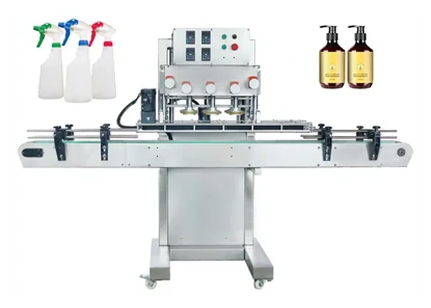
Inspection plan
Each inspection method sees a different part of the finished pack. Combine methods only where the quality plan requires them.
| Pack condition | Possible inspection route | Important limitation |
|---|---|---|
| Missing cap | Presence sensor or vision check after the capping station. | Presence does not prove that the thread has started or the closure is tight. |
| High, tilted or crooked cap | Height sensor, profile measurement or camera referenced to a stable bottle datum. | Bottle-height and neck-finish variation must be included in the accepted tolerance. |
| Wrong cap, colour or visible feature | Vision inspection using controlled lighting and approved references. | Reflections, printing, colour batches and cap orientation can change the image. |
| Tamper band or visible liner feature | Targeted side or multi-view inspection where the feature can be seen. | A hidden or internal seal condition cannot be inferred from an obscured view. |
| Surface marking or damage | Vision or sampled visual inspection against an agreed cosmetic standard. | Low-contrast marks and decorative finishes need representative production samples. |
| Closure integrity | Sampled torque, opening, leakage or product-specific pack testing. | Functional integrity is not always measurable on every bottle in line. |
Reject control
The line-control sequence should be agreed with the capper, conveyor and downstream equipment rather than added after commissioning.
Use a stable trigger, bottle reference and inspection window. Record which defect caused the failure rather than combining every fault into one alarm.
Maintain bottle identity between the inspection point and reject device through the expected conveyor spacing, stops and restarts.
Move the failed bottle to a controlled location and confirm the reject action. Define what happens if confirmation is missing.
Agree whether repeated failures alarm, stop the capper or stop the wider line so an uncontrolled run of suspect packs cannot continue.
Test bottles already between the detector and reject device when the conveyor stops, backs up or restarts.
Keep accepted references, rejected examples, settings and challenge-test results with the format record.
Acceptance evidence
A meaningful test includes normal production variation and known defect examples without relying on an improvised demonstration.
Use several accepted bottles from normal component supply, including the range of bottle height, colour and surface condition expected in production.
Prepare controlled missing, high, tilted, wrong-cap or damaged examples only where they can be created and handled safely.
Test normal running, accumulation, stop, restart, reject-bin full and loss-of-confirmation conditions defined for the project.
Buyer questions
The right answer depends on which defects are visible and which pack functions need a separate test.
No. A camera can assess visible features such as cap presence, position, height, tilt or damage, but it cannot directly prove the tightening torque or hidden sealing condition. Use the camera result with the agreed sampled torque, opening or leakage method.
A high cap sits above the approved seated reference for that bottle-and-closure format. It may indicate an incomplete thread start, cross-threading, obstruction, liner behaviour or a dimensional mismatch. The accepted limit should be based on measured good packs, not a generic height.
The control system associates the inspection result with the bottle position and advances that identity with conveyor movement until the reject device operates. The design must also account for gaps, accumulation, stops and restarts so the wrong bottle is not removed.
Cap inspection is often easiest where the closure and bottle datum remain visible, but the correct position depends on line layout, label obstruction, conveyor stability and reject access. Define the inspection view and reject point while the line layout is still being planned.
Provide accepted packs, normal production bottles and caps, component variation, filled-weight samples and controlled defect examples that represent the actual rejection rules. Also provide the required line speed, spacing, stop/restart behaviour and quality-record expectations.
Related guidance
Use the relevant page to define the pack, failure modes and control handoffs.
Combine visual, dimensional, torque and pack-specific functional evidence.
Trace high, loose, marked or cross-threaded caps to the correct process stage.
Reserve stable presentation, reject access and control interfaces before installation.
Send accepted packs, known defects, line layout and the current quality method so Lancing can review where cap inspection fits within the capping project.