01
Normal operation
Prevent reach into rotating heads, belts, transmissions and other dangerous parts while keeping the intended bottle and cap route functional.
UK machinery safety
Review the capping head, spindles, belts, conveyor, cap feeder and every intervention task as one installed machinery system. Final safeguards depend on the site-specific risk assessment.
Answer first
A screw capping machine should be selected, installed and used through a site-specific risk assessment that covers the rotating capping head or spindles, conveyor and side-belt nip points, cap feeder, bottle handling, stored pneumatic or electrical energy, access for changeover and the tasks used to clear faults. Guarding, emergency stops, isolation, information and training must work as one system.
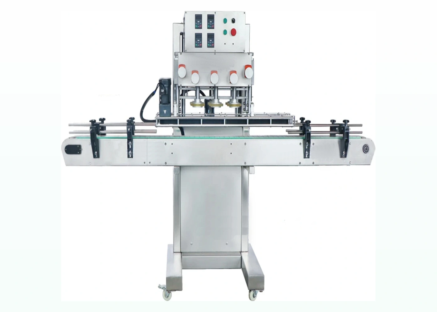
Risk boundary
Normal running is only one operating state. Many risks arise during adjustment, replenishment, blockage recovery and maintenance.
| Area or task | Typical issue to assess | Evidence to agree |
|---|---|---|
| Capping head, chuck or spindle contacts | Rotating parts, pinch points and unexpected movement during setup or fault recovery. | Guarding method, safe setup mode, stopping behaviour and access procedure. |
| Side belts and conveyor | In-running nips, trapping between moving and fixed parts, bottle breakage or unstable packs. | Guard coverage, transfer gaps, emergency-stop access and controlled restart. |
| Cap feeder, chute and escapement | Moving feeder parts, stored caps, jams and access to the handover point. | Interlocks or isolation method, low-level handling and documented jam recovery. |
| Pneumatic or electrical adjustment | Stored energy, unexpected actuation or incorrect re-energisation. | Isolation points, energy dissipation, verification and authorised task method. |
| Cleaning and changeover | Guards removed, wet or contaminated surfaces, sharp broken components and repeated access. | Safe system of work, tooling identity, inspection and controlled first-off restart. |
| Integrated line controls | One machine stopping while another continues, missing status signals or unsafe restart after accumulation. | Line responsibility matrix, emergency-stop zones, permissives and SAT challenge tests. |
Safeguarding
Do not use an emergency stop as a substitute for preventing routine access to dangerous parts.
Prevent reach into rotating heads, belts, transmissions and other dangerous parts while keeping the intended bottle and cap route functional.
Where operators need regular access, define the interlocked or controlled access method and prove that movement stops before the hazard can be reached.
Provide isolation and a safe method for tasks that cannot be completed with guards in place. Do not rely only on a control stop where stored energy remains.
Place emergency-stop devices where they can be reached for foreseeable emergencies and test their effect across the defined machine or line zone.
Use the supplied instructions, site procedures and format records to train operators, changeover staff and maintenance personnel for their actual tasks.
Set the inspection frequency from risk, use and manufacturer guidance, then retain the required records and correct defects before release.
UK guidance
These HSE sources explain employer duties and the need for safe inspection, maintenance and cleaning arrangements.
HSE’s overview covers suitability, safe use, maintenance, inspection, protective measures, controls, isolation, information and training.
Use risk, installation conditions, deterioration and exceptional events to determine when inspection is required and who is competent to perform it.
Plan maintenance so machinery cannot start unexpectedly and the equipment is returned to a safe, serviceable state.
Buyer questions
Machine documentation and marking do not replace the user’s assessment of the installed application.
No. Product conformity information is relevant when machinery is supplied, but the employer or person controlling work equipment still has duties for suitability, installation, safe use, maintenance, inspection, information and training in the actual workplace.
No. An emergency stop is a supplementary measure for an emergency; it does not prevent routine access to a dangerous part. The risk assessment should first determine how access is prevented or controlled during normal operation and foreseeable intervention.
The project should identify one responsible party for the complete line safety function and define the boundaries between the capper, conveyors, feeder, filler, labeller and reject equipment. The effect of each stop and restart must then be tested at site acceptance.
Use a task-specific safe system based on the site risk assessment and machine instructions. The method may require stopping, isolation and dissipation of stored energy before access. Bypassing a guard or reaching into moving equipment to save time is not an acceptable recovery method.
Retain the risk assessment, training and authorisation records, inspections required by the assessment, maintenance history, safety-function tests, modification records and any defects or corrective actions. The exact record set depends on the equipment and site system.
Related guidance
Use these pages to prepare the installed machine and its operating procedures.
Plan access, conveyor handoffs, guarding boundaries and utilities before installation.
Control tooling, wear, settings and release checks after maintenance work.
Define cleaning zones, safe access, contamination controls and first-off release.
Send the line layout, operator tasks, access needs and surrounding equipment so Lancing can review the machinery scope alongside the site’s competent risk assessment.