S
Speed
Approx. 20–40 bottles/min
Compact Series
A compact screw capper for labs, pilot rooms and space-limited production areas. It is suitable for standard screw caps, spray closures and pump caps where a small footprint and clean changeovers are important.
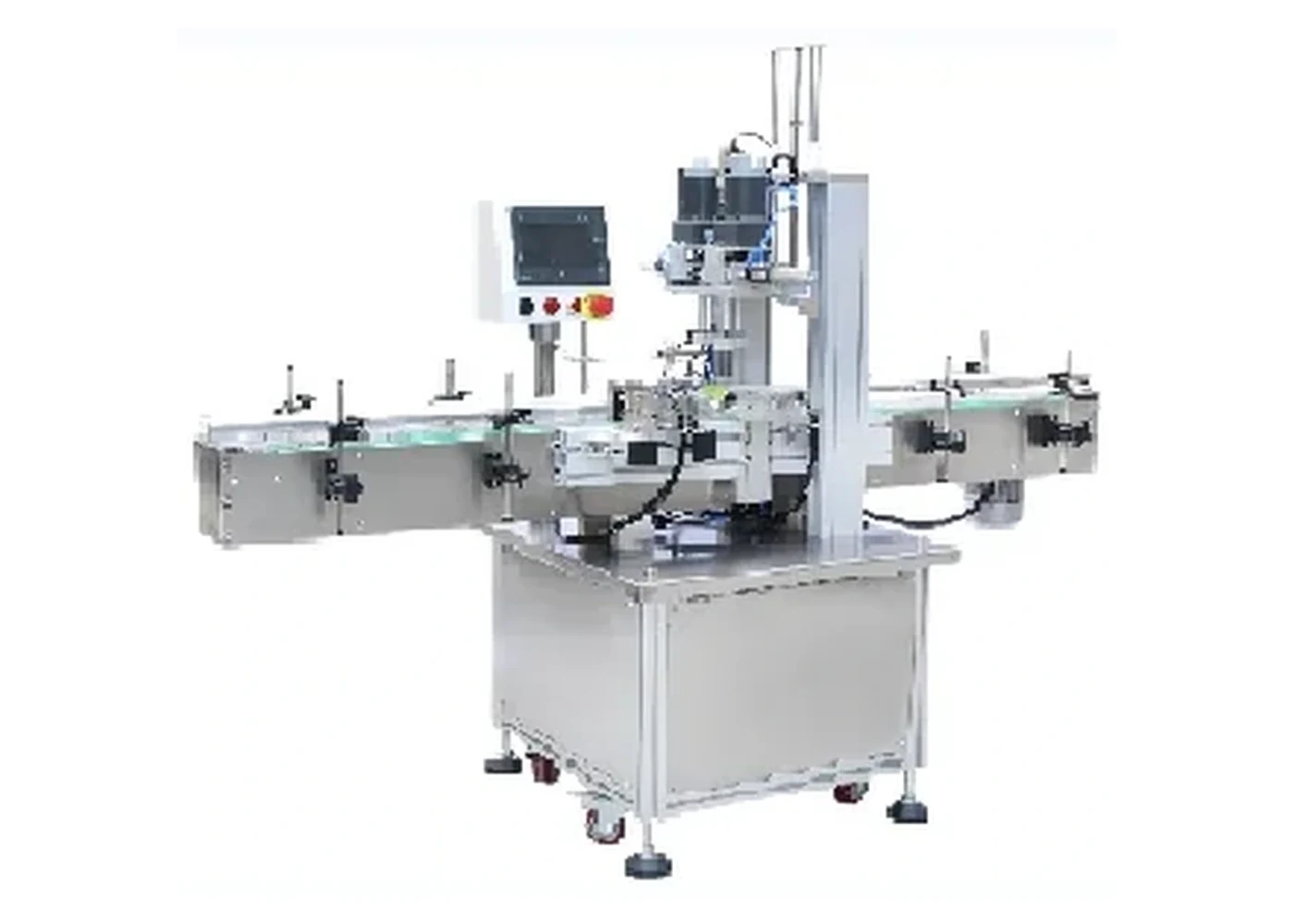
Machine overview
Space-saving screw capper for sprays, pumps and standard screw caps on compact production benches.
Approx. 20–40 bottles/min
18–70 mm caps
60–270 mm bottle height
Ideal for benches, labs and compact packaging lines.
Consistent torque on screw caps, sprays and pump closures.
Guide and height adjustments help speed up format changes.
Can be supplied with a short conveyor for steady transfer.
| Model | LU-XG1870 class |
|---|---|
| Working voltage | AC 220/110 V, 50–60 Hz |
| Cap diameter | 18–70 mm |
| Bottle height | Approx. 60–270 mm |
| Working speed | Approx. 20–40 bottles/min |
| Working pressure | 0.4–0.6 MPa |
| Dimension | Approx. 1120 × 580 × 1110 mm |
| Conveyor length | Approx. 1117 mm |
| Application | Sprays, pumps and standard screw caps |
| Integration | Bench-top or inline with small conveyors |
Final configuration, speed and tooling should be confirmed against real bottle and cap samples. Trial results may affect the exact quote, footprint and lead time.
Gallery
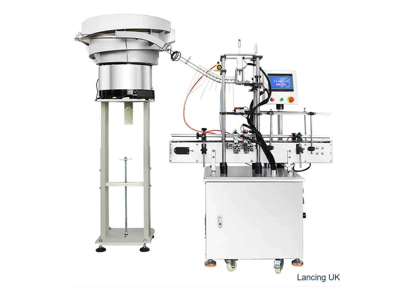
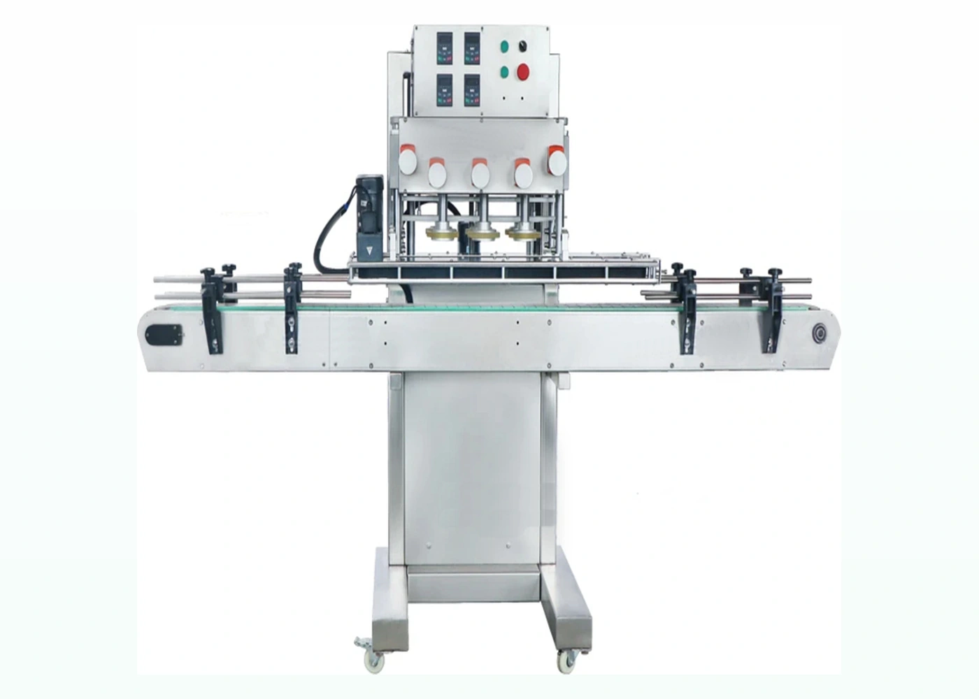
Only different machine visuals are shown here so the page does not repeat the same product photograph.
Compare
Desktop semi-automatic capper with automatic bottle clamping for low to medium volume screw-cap work.
View machine →Higher-speed inline belt capper for round plastic bottles and production screw-cap lines.
View machine →Related pages
Compare capping machinery by bottle and closure type.
For spray, pump and taller threaded closures.
Plan tightening torque and sample trials.
Technical selection
This compact route is intended for space-limited production areas that need more controlled bottle movement than a simple hand-held tool. The supplied specification covers standard screw caps, sprays and pumps, but those closure families behave differently: a low screw cap can be easy to place, while a pump or spray with a dip tube may need slower, guided presentation.
The local specification lists cap diameter from 18–70 mm, bottle height approximately 60–270 mm and working speed approximately 20–40 bottles per minute. It also lists 0.4–0.6 MPa working pressure, an approximate machine size of 1120 × 580 × 1110 mm and a conveyor length of approximately 1117 mm. All figures require confirmation against the final configuration and production samples.
Do not select from diameter alone. Record cap height, external ribs or smooth finish, liner, dip-tube length, bottle neck finish and the space needed for an operator to place the closure. The least stable bottle and tallest closure should be included in the trial.
The cap should start squarely on the bottle before tightening. Check for cocking, cross-threading and a finished cap that sits higher than the approved pack. Where a liner or sealing feature is present, confirm that the final position compresses it correctly without damage. Bottle guides or fixtures should control rotation and movement while avoiding scuffing or distortion.
Record guide positions, capping height, tooling and conveyor setting for each format. A short conveyor can help create a steady transfer, but the surrounding line still needs suitable bottle spacing and accumulation. If an automatic cap feeder is required, the cap must be tested for sorting and orientation; use Cap Feeders UK for the specialist feeder route rather than assuming the base compact machine includes it.
Provide bottles empty and at production weight, caps from normal supply, all pump or spray variants, target output, batch size, available footprint, power and air. Define how the finished pack is accepted: torque or opening result, cap height, liner condition, leakage and appearance. The thread-engagement guide and line-layout guide help prepare the review.
Buyer FAQ
The supplied configuration combines a small inline or bench-oriented capping platform with short conveyor handling, reducing footprint compared with a larger automatic line.
No. The closure height, dip tube, thread start and presentation method still require sample testing. Taller or unstable closures can change handling and achievable output.
It is an approximate, format-dependent screening figure. A timed run with production bottles, caps and the intended placement method is required for the project result.
The stated diameter range does not remove the need for suitable tooling and adjustments. External cap geometry, height, liner and surface finish can require different contact parts.
The listed 0.4–0.6 MPa working pressure supports the pneumatic functions of the configured machine. Available air quality, connection and consumption must be confirmed in the quotation.
Choose a larger single-head or spindle route when the compact platform cannot provide the required cap feeding, bottle control, accumulation or sustained line output.
Compact-line validation
The LU-XG1870-class machine is compact compared with a larger automatic line, but its practical footprint also includes infeed and outfeed space, cap presentation, operator access, compressed-air service and room to make safe adjustments. A machine that fits the floor plan can still be unsuitable if bottles queue badly, pumps overhang the guides or the operator cannot replenish caps without interrupting production.
Standard screw caps may be placed more easily than pumps, sprays or closures with long dip tubes. Test how each closure reaches the bottle, whether the thread starts squarely and whether the cap remains stable before the tightening head engages. Where the closure must be placed manually, include the operator cycle in the output trial. Where a feeder is proposed, test the feeder, chute and handover as one system.
| Interface | What to confirm | Why it matters |
|---|---|---|
| Infeed | Bottle spacing, guide entry, transfer height and recovery after a stop. | Closely packed or unstable bottles can arrive at the capping point out of position. |
| Capping zone | Head height, cap clearance, bottle support, closure overhang and access to adjustment points. | Tall pumps and sprays can collide with guides or tilt before the thread engages. |
| Outfeed | Finished cap height, downstream clearance, accumulation and handover to labelling or inspection. | A correctly capped bottle can still jam if the next machine does not accept the final pack envelope. |
| Changeover | Approved settings, parts identification, cleaning access and first-off checks. | Repeatable format records reduce trial-and-error and help protect cap and bottle surfaces. |
The published cap and bottle ranges are screening limits. Confirm the least stable bottle, the tallest closure, the smallest and largest cap contact surfaces and every format that changes the guide or head setting. Record cap height, thread engagement, appearance and the agreed opening or torque check after normal line stops as well as during steady running.
If the compact system will connect to a filler, coder or labeller, provide conveyor height, direction, available accumulation and control requirements with the enquiry. For broader line integration use capping-line layout review. For difficult pumps and trigger closures compare the pump and trigger capping route before fixing the compact layout.
Compact cell planning
A small footprint is useful only when the operator can reach the infeed, cap-placement point, controls and outfeed without creating unstable bottle handoffs or difficult clearing after a stop.
Confirm how bottles arrive, separate and locate under the capping head. Short conveyors still need stable transitions and enough space for the least rigid format.
Define whether caps are placed by hand, pre-placed upstream or supported by a feeder. Pump and spray closures need clearance for the actuator and dip tube.
Provide a clear route for removal, cap-height or opening checks and transfer to labelling, sealing or packing without back pressure at the capper.
Record electrical and air availability from the verified machine specification, plus safe access for adjustment, cleaning and minor fault recovery.
Keep approved guide, fixture, head-height and tool settings with each bottle-and-cap combination.
Measure accepted packs while the operator performs normal loading, cap supply, inspection and stop/restart tasks.
Question-led guidance
A compact machine still needs a controlled bench, utilities, operator route and production handover.
Yes when the layout gives safe access, clean bottle transfer, suitable utilities and enough space for the operator to place caps and remove finished packs. The filling process must not leave product on the closure contact area. Use the utilities and interface guide to define the cell boundary.
The pump must be presented so the dip tube enters the bottle without bending, catching or lifting the closure off the thread start. Tube length, curvature, bottle neck and operator method must be trialled together. Automatic feeding may require a dedicated handling route rather than standard cap presentation.
Yes. The support surface must keep the machine level and stable under the normal capping cycle, while providing suitable access and utilities. A moving or flexible bench can change alignment and operator handling even when the capping head settings are unchanged.
It may be possible, but each location must provide the correct utilities, stable support, access and approved setup. Record the height, tooling, guides and first-off checks so moving the machine does not turn every batch into an uncontrolled new installation.
Send representative samples, target output and the current acceptance method so Lancing can review the correct capping route.
Compact production cell
A compact footprint is useful only when the installed cell still gives stable bottle presentation, safe access and repeatable first-off release.
Confirm a stable support, machine access, electrical and air routing, cap and bottle staging and a clear finished-pack path.
Define which chuck, guide, clamp and surrounding surfaces contact the pack or product residue and how each can be cleaned safely.
If the machine moves between areas, recheck level, services, settings, guarding, bottle support and accepted first-off packs before use.
Compact-format control
A compact capper can support several formats, but a similar bottle or cap diameter does not prove that the same chuck, guide or setting is suitable. Build the changeover plan around the complete bottle-and-closure interface.
| Format evidence | Compact-cell implication |
|---|---|
| Bottle and closure drawings | Confirms thread, sealing land, cap height, grip surface and likely tooling family. |
| Filled production samples | Shows bottle stiffness, stability and access around the neck at normal working weight. |
| Approved finished packs | Defines cap position, opening evidence, liner or tamper condition and appearance. |
| Change-parts record | Prevents similar-looking chucks, inserts and guides being mixed between formats. |
| Torque test method | Provides a repeatable release check after adjustment, cleaning or tooling change. |
A compact machine proposal should be reviewed with its supporting bench or stand, incoming bottles, cap supply and finished-pack collection. Mark the space needed during normal operation and changeover, not only the quoted machine dimensions. Ask the supplier to identify the final arrangement offered for the selected pack.
Where a short conveyor is proposed, include the loading and discharge tasks in the demonstration. Clarify which operations the operator performs and which are automatic. Use the actual bottle and closure range to establish whether the compact layout meets the practical batch requirement.
Confirm the installed dimensions, support requirements, services and operating clearances for the actual offered configuration. Provide the proposed work area and request a layout review before treating a catalogue footprint as an installation approval.